How P&IDs become intelligent schematics
Powerful symbol properties turn simple P&ID’s into intelligent process diagrams
Plant design encompasses many areas of responsibility. One such area is process design which involves the creation of Piping & Instrumentation Diagrams (P&IDs). These important process diagrams are fundamental to the design process.
When designing plant, process diagrams are used to illustrate the chemical process and the equipment used. When complete they fully define the process and contain detailed information about the individual components utilised in the process.


Process Diagrams define the process
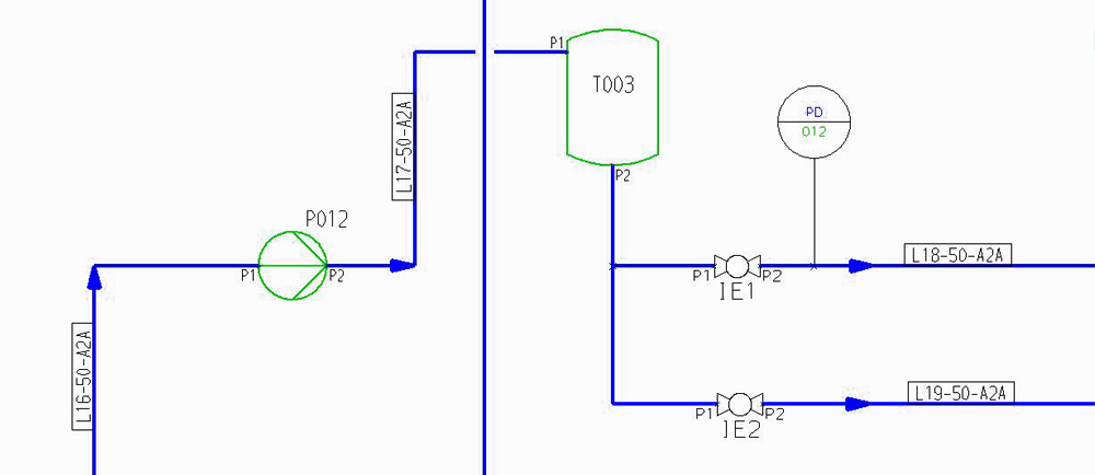
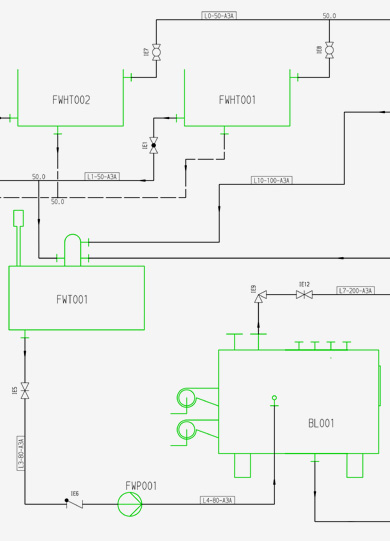
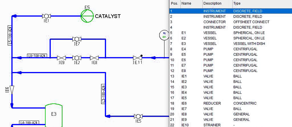
Process diagrams use standardized graphical symbols to depict process equipment and instrumentation. For example, symbols will typically be used to represent tanks, pumps, gauges, valves, reducers, and other types of piping component.
Symbols are connected by simple lines which represent the pipework. These lines also illustrate how fluids flow through the system. In addition, the process diagram may contain other important information such as materials, operating pressures and temperatures. This information can appear as text on the process diagram or be displayed in a table.
The lines connecting the symbols also have properties such as nominal size, pressure, material, specification and insulation. A key challenge when documenting a process is to capture all of the detailed information as quickly and accurately as possible when creating the process diagram.
Process diagrams with hidden detail
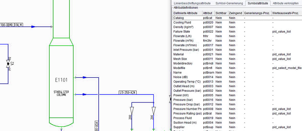
Conventionally, not all of the above information is shown on a process diagram, but it still has to be captured somewhere for later use. The solution to this challenge is attributes. Attributes are invisible properties that can be applied to individual components, pipelines and instruments. They can be queried and amended as often as required. Attributes can be set to user-specified or pre-defined values, and can be automatically output to parts lists or customizable reports at any time during the design process.

Attributes – the key to intelligence
Attributes are a very powerful tool because they turn traditional P&ID schematics into intelligent design documents. The resulting process diagrams are no longer mere graphical representations, they become a rich source of analysable, reportable design data that can be used to support downstream tasks, such as parts listing, cost analysis and procurement.
The power of attributes
M4 P&ID FX is a P&ID system that fully exploits the power of attributes to capture your design data via a simple user interface. The software is optimised specifically for the task of P&ID design, and enables you to quickly represent your processes graphically while embedding your detailed design data within the P&ID.

Conclusion
CAD Schroer’s P&ID software is highly affordable. The software gives a rapid return on investment, typically paying for itself over the course of the first project.
P&ID software for professional process design – M4 P&ID FX
FAQ – Frequently asked questions on P&IDs
When designing a plant, P&ID’s are used to illustrate a chemical process and the equipment used. When complete they fully define the process and contain detailed information about the individual components utilised in the process.
P&ID is an abbreviation of Piping and Instrumentation Diagram and is a term from process engineering, a part of plant design. A P&ID describes a process or a process plant in simplified schematic form. It shows the main process equipment, the interconnecting pipework, and flow direction.
Plant design encompasses many areas of responsibility. One such area is process design which involves the creation of Piping & Instrumentation Diagrams (P&IDs). These important diagrams are fundamental to the design process.
P&ID’s use standardized graphical symbols to depict process equipment and instrumentation. Symbols will typically be used to represent tanks, pumps, gauges, valves, reducers, and other types of piping component. Symbols are connected by simple lines which represent the pipework. These lines also illustrate how fluids flow through the system.
Intelligent P&ID’s are best created with M4 P&ID FX, a specialised program for professional P&ID design. CAD Schroer’s P&ID system is affordable for any company and typically pays for itself after the first few projects.
